(Stillness in the Storm Editor) The following is a detailed overview of how a UFO or extraterrestrial spacecraft works, particularly focusing on the use of intersecting electromagnetic fields to produce propulsion.
This is a fascinating yet extremely difficult article to read. The grammar isn’t perfect, the author appears to have a background in technical and scientific writing, and the descriptions are rather hard to follow. That being said, if you can work through these things, there’s a wealth of knowledge and understanding to glean.
– Justin
Related These Are Real Pentagon Reports On Warp Drive, Extra Dimensions, Anti-Gravity, And More
by Paul E Potter,
| The most comprehensive collection of technical drawings and detailed descriptions of how some types of UFOs work are to be found in the “Andreasson Affair” books (see bibliography page). The extra drawings and descriptions by Betty Andreasson (now Betty Luca) published by her recently have, I feel, especially helped this new branch of research into how these flying craft actually might work, and how they might be replicated in the future. For those who have seen this webpage before on this website you will notice many new facets in this latest theoretical study of how these particular craft work, there will no doubt be even more discoveries to come as time progresses. 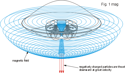 I believe now that at the heart of the Andreasson type UFO use is made of very powerful magnetic fields, generated by the craft to expand outward into the air surrounding these flying discs, to alternately energise and store a vast amount of electrical energy in one magnetic field, and then to force that vast store of energy back into the center of the craft, by collapsing that field, and with another magnetic field transverse to it, to densify and redirect that vast store of electrical energy out and down through the craft’s center – to transform that electrical energy into a propulsive force of great velocity and power. I believe now that at the heart of the Andreasson type UFO use is made of very powerful magnetic fields, generated by the craft to expand outward into the air surrounding these flying discs, to alternately energise and store a vast amount of electrical energy in one magnetic field, and then to force that vast store of energy back into the center of the craft, by collapsing that field, and with another magnetic field transverse to it, to densify and redirect that vast store of electrical energy out and down through the craft’s center – to transform that electrical energy into a propulsive force of great velocity and power.That both magnetic fields are alternately generated and then collapsed, and that they oppose each other, ensures a continual movement and excitation of electrical energy – and consequently a very visible generation of high energy photons around them. Hence, when these craft are energising their electric fields colored light and white light are given off as the sea of electrons changes in speed and direction. |
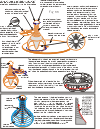
The Andreasson UFO shipThe drawings of the overall shape of the UFO craft published in the first of the Andreasson Affair books were slightly misleading (see fig.1) but as the additional publications of the Andreasson Affair series progressed a greater insight into the craft’s shape and indeed it’s internal functions could be appreciated,  and when Betty Luca’s most recent booklets were published by her in 1999, which included detailed drawings of the craft’s ‘power system’ a much more comprehensive understanding of their workings could be gleaned (see fig.2). It will be to those internal functions of the UFO craft’s power system and the generation of the magnetic fields it utilizes that this webpage will be dedicated. and when Betty Luca’s most recent booklets were published by her in 1999, which included detailed drawings of the craft’s ‘power system’ a much more comprehensive understanding of their workings could be gleaned (see fig.2). It will be to those internal functions of the UFO craft’s power system and the generation of the magnetic fields it utilizes that this webpage will be dedicated.
While the top section of the craft, the section which contains the various medical examination rooms, the human transporting chamber, and the actual control center that the ETs use to operate the craft are very interesting, and are amply described in the various Andreasson books, I consider the lower part of the craft where the electrical energy is generated and manipulated to be even more interesting. In the lower part of the craft are, fundamentally, two co-operating components; one – the large toroidal shaped casing which generates the main magnetic field and two – the rotating assembly of spherical conductors which collapse the main magnetic field and generate a central magnetic field that forces charged particles through the base of the craft at great velocity. Most of the structures of these craft are made from aluminum or aluminum alloy, sometimes laminated with other materials to aid their conductivity or storage of electric charge, and sometimes formed with a honeycomb structuring for strength and lightness. Also in theAndreasson type of UFO some of the components are formed from a glass/quartz like material so as to take advantage of their intrinsic dielectric or semi-conducting qualities. But, as with all things made by ‘aliens’ of an advanced scientific wisdom, whatever material they have used appears to have undergone rigorous modification so as to facilitate an enhancement of that material’s fundamental attributes, for example; the glass/quartz spheres which rotate in the center of the craft are embedded with metal rods or wires to modify the way electric charge reacts to such material normally; fluids are used for their electromagnetic qualities when circulated through their casings; gases also for their polarizability when circulated through their casings. It’s alien engineering but engineering that is not too distant from our own – and the basics of it are certainly understandable in our realms of physics. The toroid
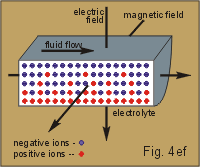
Contained inside the toroid is an electrically polarizable fluid that when rotated round the toroid generates a magnetic field that extends far outside the craft – exactly what that fluid is contained inside the toroid is subject to further research, possibly it is a gas in the form of deuterium gas (deuterium can be electrolyzed out of water as a ‘heavy hydrogen’ gas and separated from the oxygen of water) which can be ionized by passing an electric current through it (see note 1). It could be that the toroid holds a liquid as simple as water modified in such a way as to be insulating, but carrying metallic suspensoids so as to generate electrical charges. In all cases the toroid would need to be made of an insulating material, perhaps a metal like aluminum laminated with insulating skins (see note 4). This would be necessary to prevent electric charge leaking away from the inner fluid through the toroid’s casing. Also, if the casing were of an insulating material diffuse layers would form on the outside surfaces of the toroid opposite in polarity to the fluid inside the toroid. As soon as the fluid generated an electric current, and a magnetic field, there would then follow a Lorentz force As mentioned above, electric charges cannot be conducted directly from the charge-accumulating fluid of the toroid, through it’s walls and corners, there will however be a capacitive effect which will accumulate charges of an opposite polarity, on the outside surfaces which will correspond to the inner ones in intensity and location. Thus there would be a build-up of positive charge on the top-inner corner of the toroid outside the casing (and a build-up of positive charge on the outside of the top-outer corner), and correspondingly, a build-up of negative charge on the outside of the bottom-inner corner, throughout their circumferences. These diffuse layers of electric charge occur most effectively when the liquid is moving, and the faster the polarized fluid moves inside the toroid the more pronounced will be the separation effect of the electrical ions of the differently moving outside diffuse layers of the toroid.
This revolving positive field inside the craft helps create an electric sink for the normal air outside the craft to initiate an inflow, through the craft’s circumferential duct, of polarized and neutrally charged air which, as soon as it passes through the aerodynamically-shaped craft’s circumferential duct and over the toroid’s electrically-charged outer edge, becomes ionized from the effect of sharp-edge ionization (see fig.5). The duct is especially designed to provide an upper curved surface to act as a constrictor of air flow to speed up the air flow (like a venturi) under it to thereby create a low-pressure area inside the duct, and also to move the incoming air directly over the toroid’s ionizing sharp edge.
This Coriolis thrust upon the electrons will also exert on them a centrifugal force increasing their mass by several thousands (see note 6) as they spin outside the UFO (for a more detailed, and scientific, description of this phenomenon of spiralling electrons out into an external electrical sheet around a UFO see the excellent paper “Magnetic Vortex” by Vencislav Bujic).
Buy Book Secrets of Antigravity Propulsion: Tesla, UFOs, and Classified Aerospace Technology Crystal sphere-sets
Buy Book Secrets of Antigravity Propulsion: Tesla, UFOs, and Classified Aerospace Technology
Through the aluminum stems between them the large lower spheres are used to transfer electric energy into the small upper spheres, for, as in electrostatics if two spheres, one large and one small, are inter-connected by a conductive link so that both spheres are at the same potential, then the intensity of charge on the small sphere will be much greater than that of the large sphere (ie density is inversely proportional to radius of curvature). Another important, and recent, discovery about these upper and lower spheres is they both revolve, about the vertical axis of the stem, presumably to ensure that when electric current is conducted by them that current is spread round the whole circumference of the sphere so as to induce a uniform magnetic field around them. Both spheres rotate at different speeds.
The large bulky shape of the sphere-sets with their large lower sphere is not cumbersome designing, but wholly relevant to how this transverse magnetic field is shaped around them and how this field works.
Collapsing field
The two magnetic fields, of the toroid and the transverse, would be made to resonate together – this creates the vector for gravity manipulation. Simple.
One more thing… That the lower spheres are said to pulsate with light, of all colors of the rainbow, is indicative of the electrical energy of the atoms and molecules in the fields of charged particles surrounding them being pummelled and stressed by the changes in the magnetic fields of the craft. Indeed, the electrical environment of whole UFO craft is so extreme that atoms in the air surrounding them undergo tremendous forces and the orbiting electrons of those atoms get thrown out of their normal energy orbits and jump in and out of their adjacent energy bands exhibiting all sorts of photon emission as they do. This throwing off of colored photons is the visual effect of extreme Fermi level energy-exchanges of when electrons are accelerated, decelerated and forced to flow in the opposite direction – phenomena which occurs at least four times every cycle of the two opposing magnetic fields energizing and collapsing. |
| other pages in this series
Physics of UFO gravity manipulation – by Paul E Potter |
Not sure how to make sense of this? Want to learn how to discern like a pro? Read this essential guide to discernment, analysis of claims, and understanding the truth in a world of deception: 4 Key Steps of Discernment – Advanced Truth-Seeking Tools
Stillness in the Storm Editor’s note: Did you find a spelling error or grammar mistake? Send an email to [email protected], with the error and suggested correction, along with the headline and url. Do you think this article needs an update? Or do you just have some feedback? Send us an email at [email protected]. Thank you for reading.
Source:
http://www.linux-host.org/energy/ufogravity.htm







Leave a Reply